|
|

|


|
Instrument Page
The conceptual design of the instrument was driven by the WEAVE science requirements, as defined by the Science Team, and translated to technical requirements by the Project and Instrument Scientists. The following table summarises the instrument characteristics:
| Specification | Requirement | Goal | Design |
|---|---|---|---|
| Field of view diameter | 2 degrees | 2 degrees | 2 degrees |
| MOS multiplex | 800 | 1000 | 964/940 |
| Atmospheric dispersion compensation | 0.4-1.0 µm, 50oZD | 0.37-1.0 µm, 60oZD | 0.37-1.0 µm, 60oZD |
| MOS fibre aperture | >=1.2" | 1.5" | 1.3" |
| Open shutter efficiency (1 hour observations) | 70% | 90% | |
| Wavelength coverage | 400-950nm | 370-1000nm | *370-960nm |
| Spectral resolution (full simultaneous coverage) | 5000 | 5000 | 5000 |
| Spectral resolution (reduced coverage) | 20000 | 20000 | 20000 |
| Stray light as function of faintest target | <1% | ||
| Blue system efficiency | 20% | 25% | 25% |
| Red system efficiency | 25% | 30% | 30% |
| Multi-IFU multiplex | 10 | 30 | 20 |
| Multi-IFU FOV | 9" x 9" | 9" x 12" | 9" hex |
| Multi-IFU spaxel size | 0.8" | >1.2" | 1.3" |
| Single IFU FOV | 3' x 3' | 1.5' | |
| Single IFU spaxel size | 2.5" | Inner 1", outer 2.5" | 2.6" |
*The focal plane of each camera is occupied by two e2V CCD231-C6 CCDs (6kx6k format). The Useful spectrograph focal plane is 8k spectral x 6k spatial. This implies a small gap between the two CCDs. At the central slit position, these gaps span 549.1-553.9nm and 759.0-766.9nm in the low resolution mode and 452.5-453.6nm ; 530.2-531.5nm and 641.2-643.1nm in the high resolution modes. The spectrograph slit is curved to match the low resolution gratings, leaving a residual curvature in the high resolution mode of around 3.5nm shift (~350 pixels) between the central and extreme fibres.
The philosophy behind the construction of WEAVE is to keep it simple but effective. Thus the design exploits the use of COTS (Commercial Off-The Shelf) components which not only reduces project costs and risks but provides an attractive solution for maintaining the instrument throughout its lifecycle.
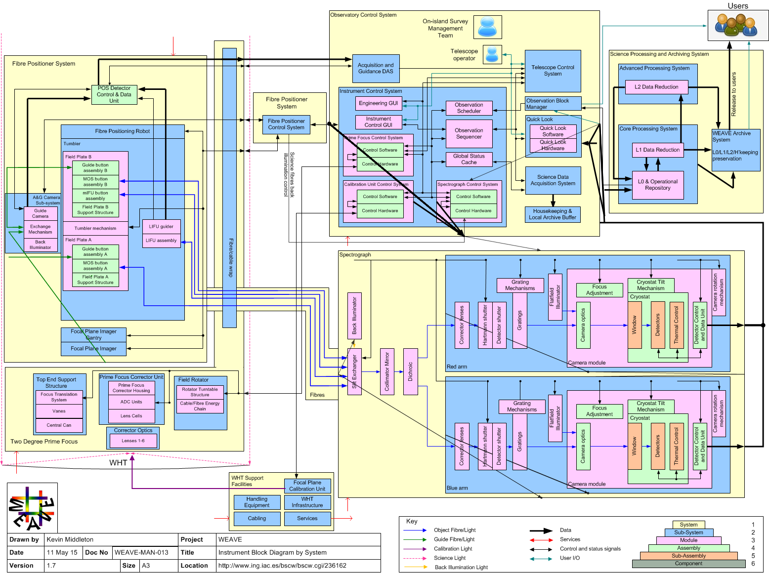
The Instrument Block Diagram
The Instrument Block Diagram provides an high-level overview of the arrangement of the systems that comprise WEAVE. For readability, detailed component information is not represented here but the flow of data and signals are shown.
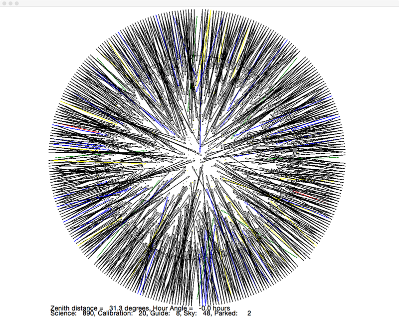
The Positioner
Pick-and-place technology will be used to position the fibre buttons onto a plate using a commercially available X-Y gantry. A computer simulation shows the complexity of weaving 960 fibres to acquire their targets. The solid circle shows the science field diameter, Green fibres are guide stars, yellow are calibration stars, blue are sky and black are targets.
At the edge of the field are the fibre retractors that tension and protect the individual fibres. Each retractor holds six fibres and the buttons are seated at the entrance to the retractors as illustrated in the following pictures.
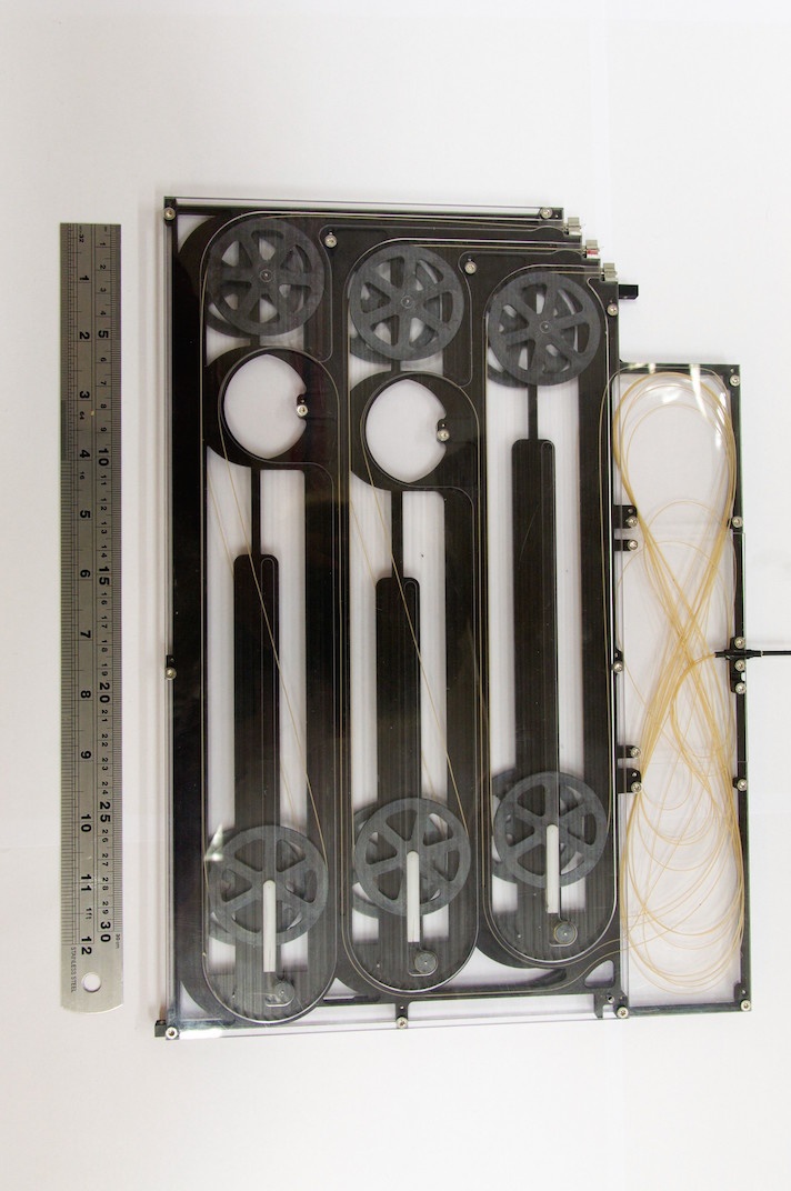
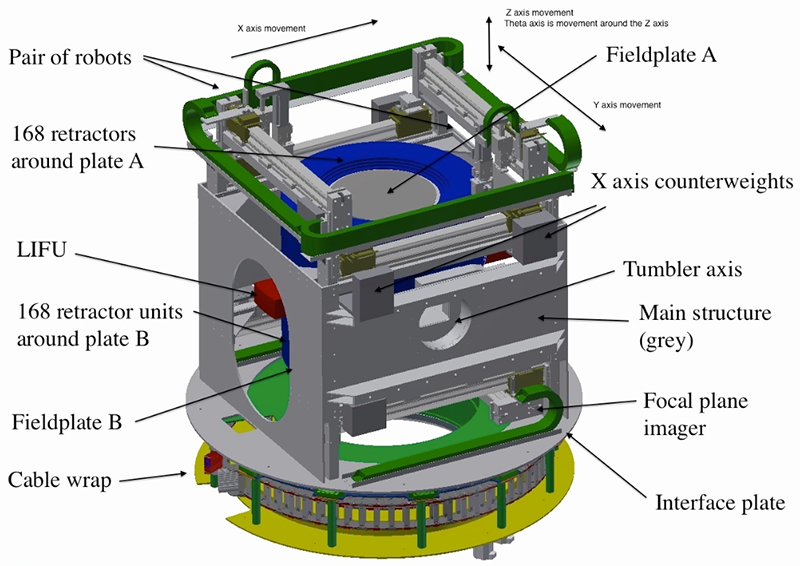
The fibre positioning mechanism is a twin-based system of fibres, retractors and buttons etc. The arrangement is such that the fibre-assemblies are positioned at each end of the rotating assembly (blue) also known as the tumbler. This fits inside a gantry with a pair of robotic grippers that place the buttons on the plate. The upper plate is configured by the robots while the lower plate sees the image plane of the telescope and diverts light from each target to the spectrograph. Fieldplate B also holds 20 small integral field units that feed an alternate input slit. A fourth slit is fed by a single large integral field unit (red box) that can be moved into the focal plane by the tumbler.
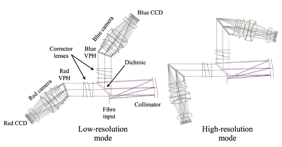
The Spectrograph
Fibres from the positioner are fed to the dual-beam spectrograph which incorporates a dichroic at ~600nm and has a grating exchange mechanism that provides either low- or high-resolution observations in each arm. The spectrograph will be housed in GHRIL.